My first shot of building a vale amplifier. I like a clear, full tone that is on the verge of breaking up so I though that a JTM45 amplifier would be cool for my first build. I also considered a 18W Marshall type, but settled for the JTM45.
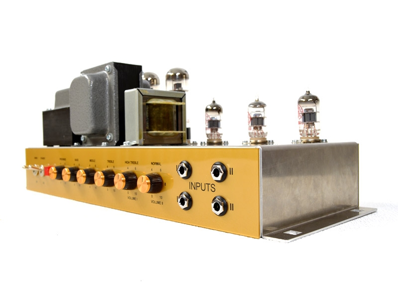
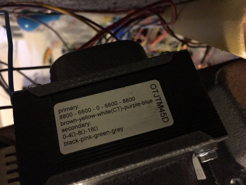
I have a Vintage Modern with KT66 so I decided to get EL34 tubes for this one. Its easy to change to KT66 in the JTM45 if I want later on. We will in that case only use a different pair of wires from the output transformer.
In summary:
The basic sound is very pleasing but I feel that the bright channel is quite bright, and it just needs a hair to add in the sparkle. Normal channel has some nice body to it. Quite clean tone with a 2 x 12″ (in total 130 watts) . I will do some mods to make it more usable, especially changing a few resistor values to tame the treble (see the JTM45 Modes page). A master volume/PPIMV seems to be a “must”.
Note! Take a step back and consider how to apply potential mods. For instance, if you will do the PPIMV mod make sure not to solder the wires from R22-R24 and R23-R25 (ref to TT JTM45 layout) underneath the board.
Below outlines the build of the original schematics.
The video below is from a JTM45 plus build by Tube Depot. This video was actually recommended by another JTM45 kit vendor as the “build instructions”. It’s a good source although it is not 100% what I will be building with the TubeTown (TT) kit. You will find links in the video to their schematics and build instructions that are good to read through to get a better understanding of how to build a JTM45 amplifier.
There are no enclosed step by step instructions from Tube Town (at least when I built it in 2017). We will have to do with the schematics and layout available as pdfs. Lucky for us, they are quite clear. The only thing I wish for is that TT would have taken a few more pictures of their own build at various steps. Now we only have the completed build and some wires are hard to see.
Layout (go to this link to tube town for images and other resources)

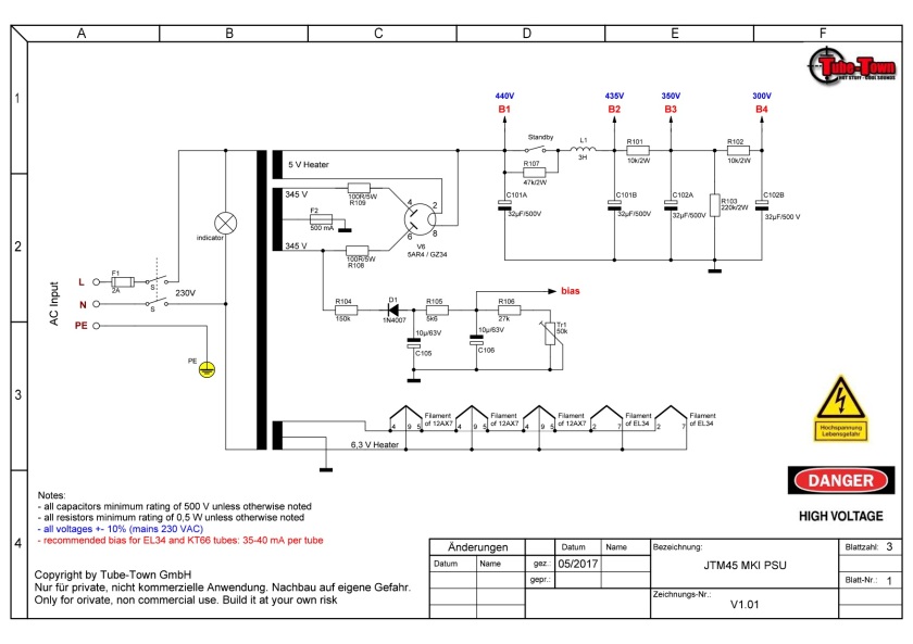
Schema
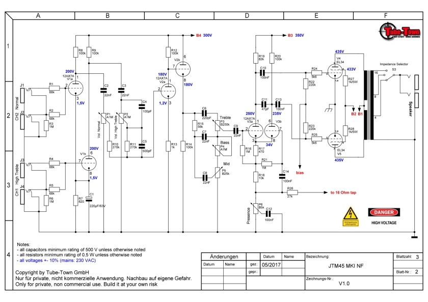
page 2
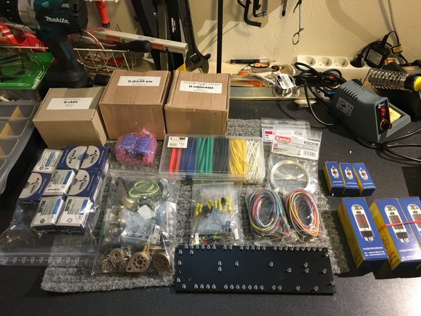
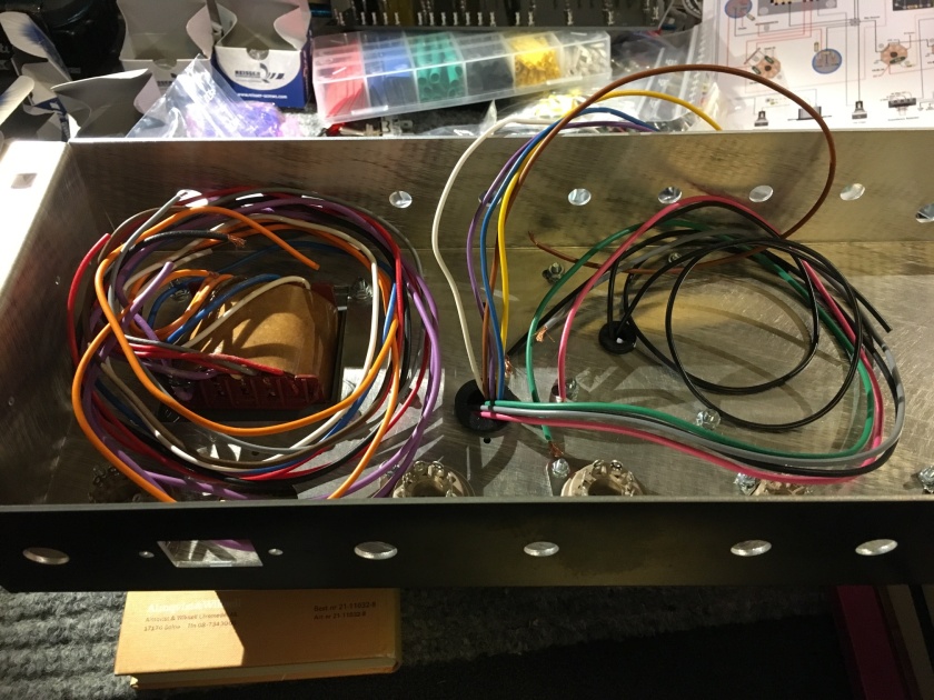
The package I received from TT was well packaged and protected. Pictures below show the contents unpacked.
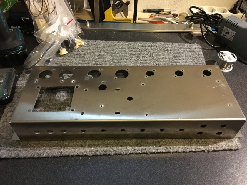
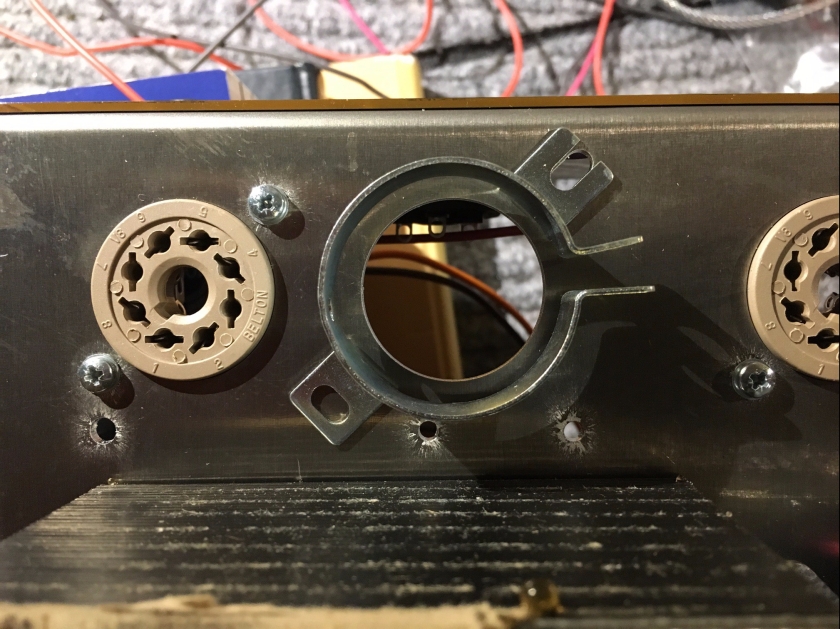
The TT chassi already had holes in the side for the capacitor drilled. TubeDepot had to drill those. I did however find that TT chassi lacked one hole for the cap holder that will be seated on top. That I had to drill with a 3,2mm drill bit and used a M3 screw to secure the cap holder.
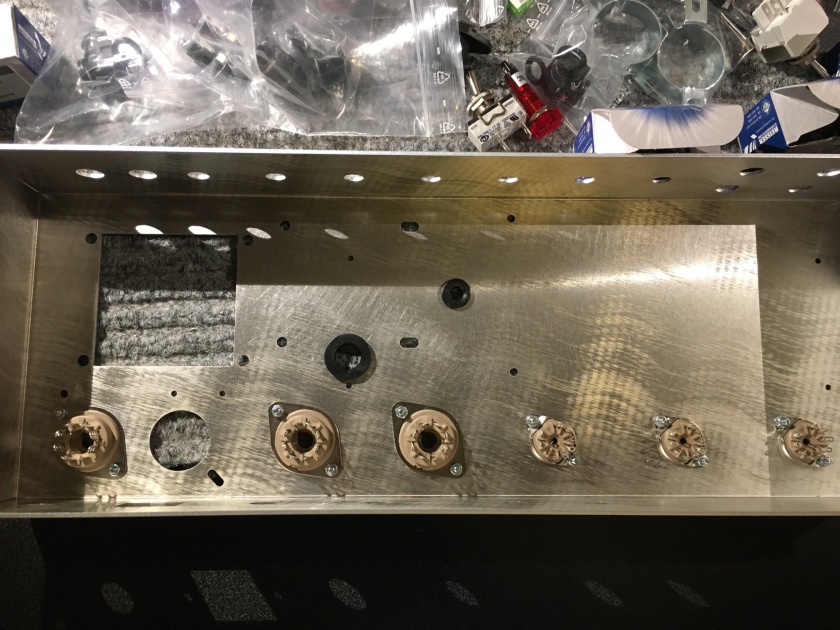
First I installed the grommets to prevent the cables from the choke and PT to cut on the chassi. The tube sockets were already attached to the tube holder. The screws, washers and nuts etc are rather small and I recommend using a small tweezer or similar as space can be a problem for fat fingers.
Before installing the transformers I recommend to add whatever need to be screwed into the chassi as it gets quite heavy and difficult to pivot later on. I did not do this and I had to pay for it 🙂 Install the ground star, cap can holder (which I talked about above) and solder terminals below (underneath) the power transformer (PT).
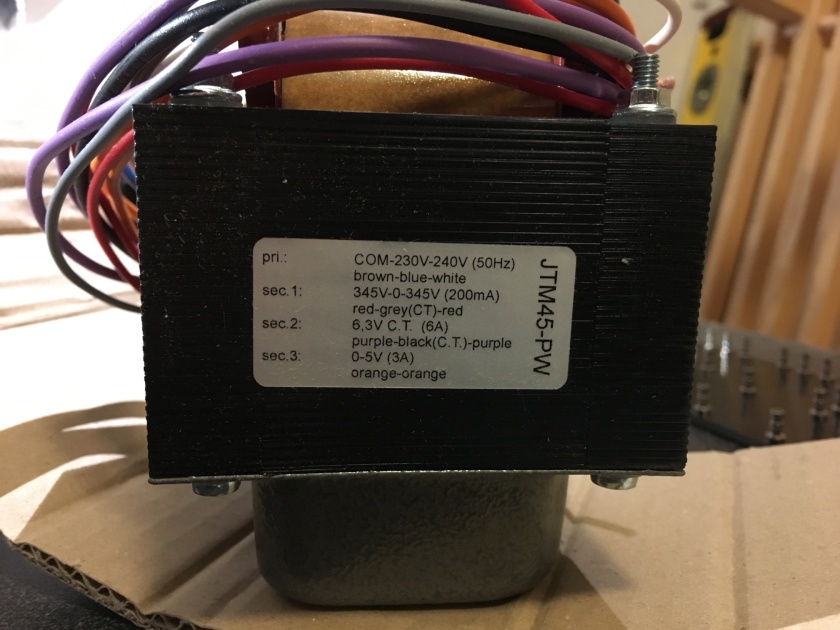
The install the power transformer. This had long screws run through the unit. I used the nuts already attached to the PT. They had to be held in place as I don’t know what would happen if they were completely removed from the PT.
Pew, that was hard work installing those heavy OT, PT (and choke) and getting the screws in place.
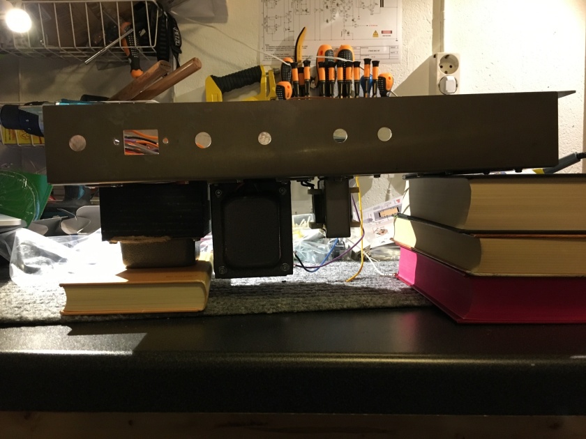
Turned it over and used a few books as a stand/leveller.
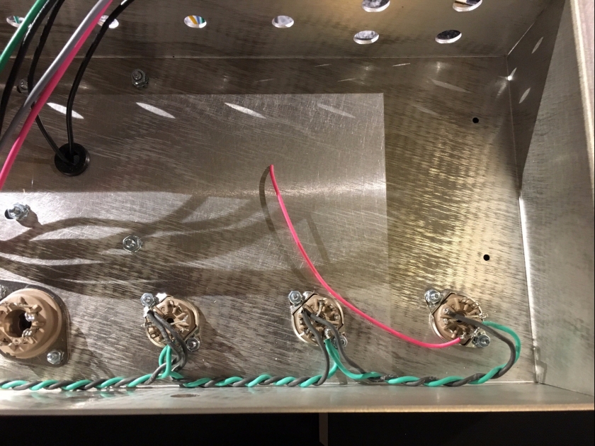
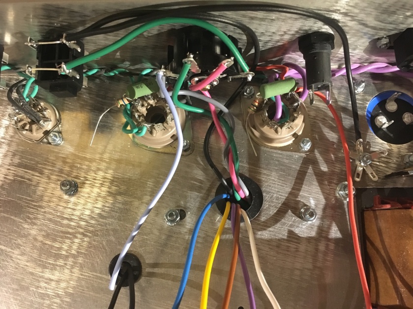
Wired el34 sockets. Think carefully in what order to install wires and resistors, it can easily be messy and hard to solder if wires are in the way. Heater 1 and 2 (purple wires) shall be installed to the last EL34 holder.
I think it was not such good idea to use the same color (green) wires as TT did for their wiring of the tube sockets, nor using just a slight difference in color for these chords in their layout . I used green/black to clearly see what goes where. I entered the tube from “above”. It would likely be easier to draw the wires to enter the pins from the side, but perhaps it would be slightly messy later when connections are made to the pre-amp board. I just had to move some wires to the side for a couple of solder points but not a big problem.
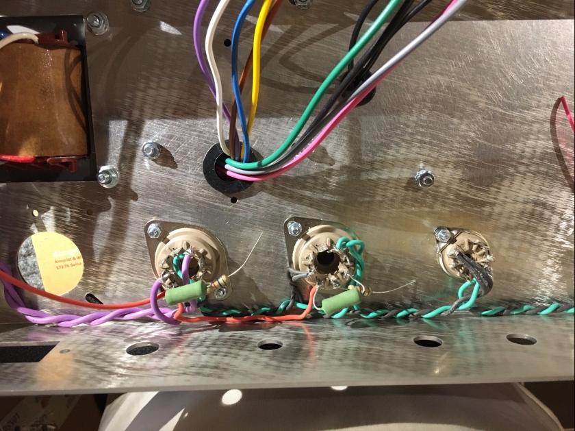
When reading about some JTM45 mods (especially at raw sewage), I’m happy to see that many of the changes that are suggested to a JTM45/reissue BluesBreaker62 are included in the TT kit. I don’t know if TT excel but it’s anyway good.
For instance the 5,6k resistor on pin 5 (on the power tubes) and the 1k/5W across pin 4 and 6. This will help reducing/removing parasitic oscillation that could kill the tubes.
Install jacks. I used one black plastic ring on the inside for each input jack.
The pots has a small ground pin to the side that has to be snipped of in order for a flush installation.
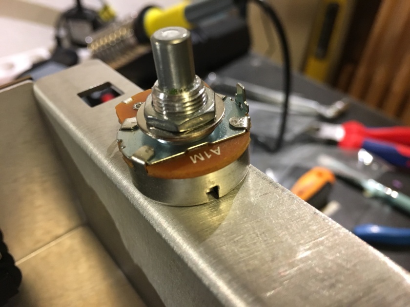
Removed pin
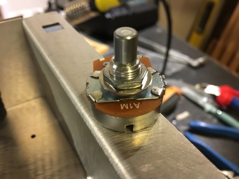
Some pots had one washed while others had two. In the end I decided to use one washer on the outside. Check the schematic to make sure you put the pots in the correct place. The two volumes and bass pot should be 1meg, treble 250k, mid 25k and presence 5k.
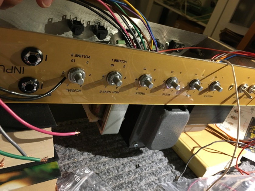
The hole for the indicator light was not drilled wide enough. Had to use a metal file to widen it just a bit. Did not take long to widen.
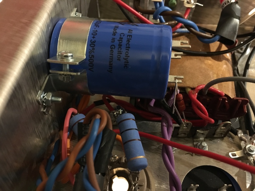
Added the F&T cap on the top of the chassi. One hole was missing in the chassi for the cap that sits on the top. used 3,2mm steel drill. First make sure to tape over the sockets so you wont get any metal debris inside them. See the picture at the beginning of this page.
F&T caps is said to be “the best” by Joe Popps. Perhaps he knows. If so, then kudos to TT to have quality components.
Their values are 32x32uF (instead of normal 50x50uF) which seems to be a standard modification to add clarity. However, it is suggested that the preamp filter capacitor could be changed to a 16x16uF. It has not been done here and I will probably wait with trying to understand if that is something I ought to change or not.
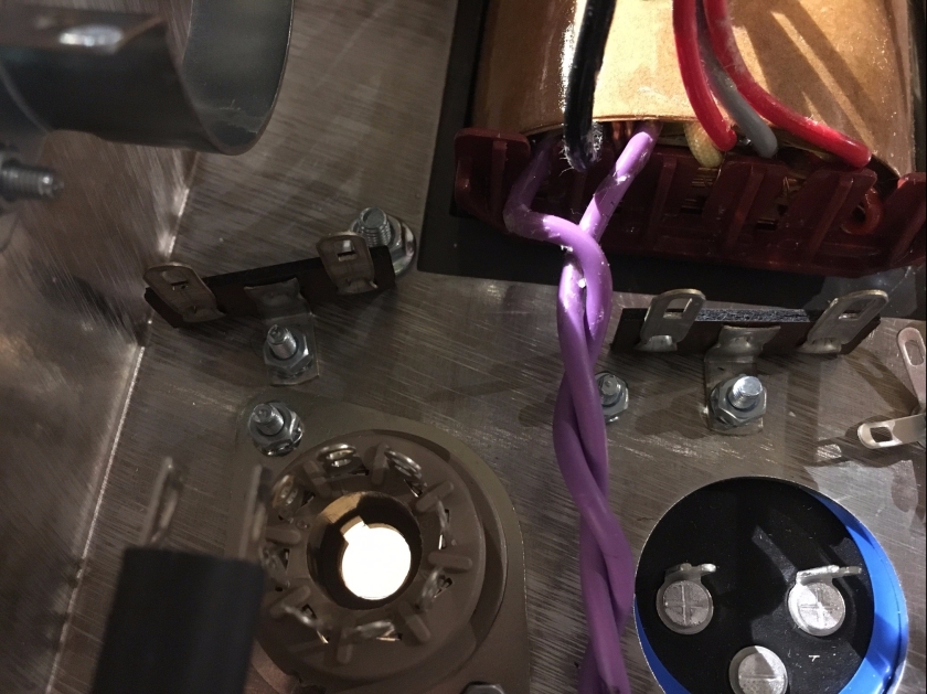
Added two solder mounts for attaching wires. It’s better to wait with the installation of side mounted F&T cap mount before this step. As I said before it should be done before installing the PT/OT and choke as it becomes rather difficult to handle the heavy box at this time.
I was searching for a “star” ground. But realised I had to make my own from parts. Use all 7 pins. I just used 5 and had to add two wires to some pins. Would have been slightly easier with more pins.
Time to wire the secondary OT to the load selector. The light blue cable from the 16 Ohm could be skipped in this step and added when the board is soldered instead. I ended up removing this wire.
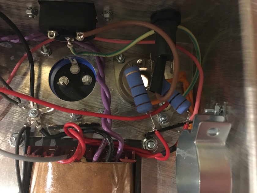
Installing the blue resistors over the rectifier tube. They are rather large and the fuse is a bit in the way. Try to install the right most angled to the right so it is out of the way. Add the fuse last here. Wires from the heater (5V) and HV1/Hv2 (High Voltage) shall be soldered to the wire support and rectifier before installing resistors and fuse. The cap holder to the right should have been installed after as well as it was in the way just a bit.
Note the green/yellow wire that I attached to the foot of the wire support. It was very difficult to understand from the TT pictures where this should be connected.
Some wire mess. They will be wired into the board later. The white power switch is up side down in the image below. Gave me some surprise when began the first tests. More about this later.
Cap installed, resistor prepared.
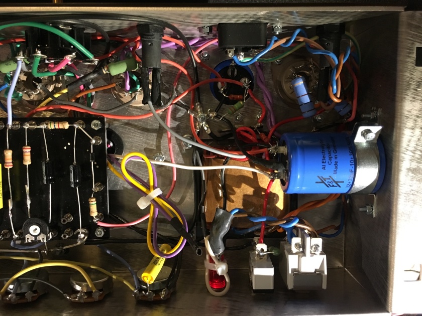
Choke and center tap OT attached. Cap below wired as well.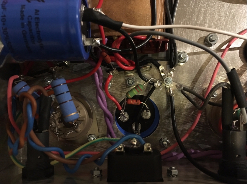
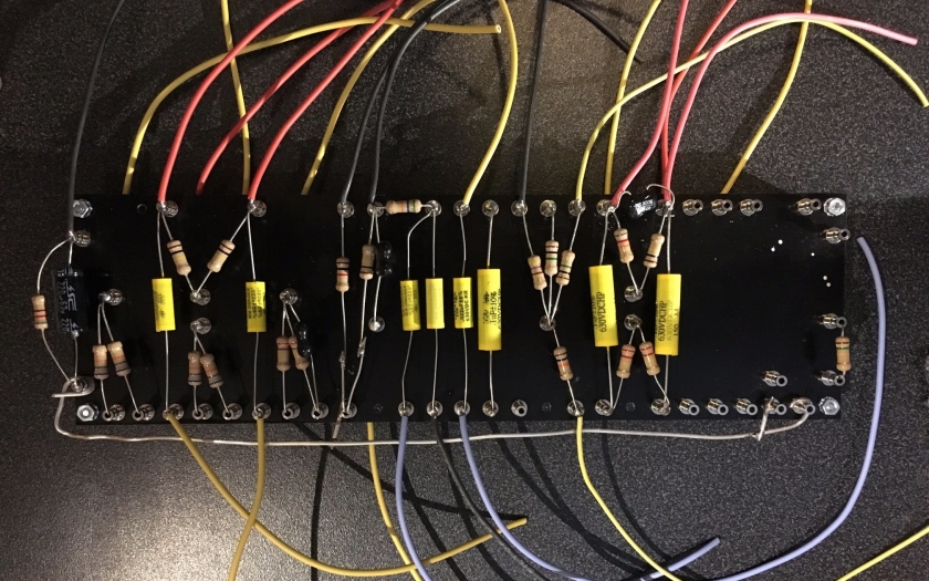
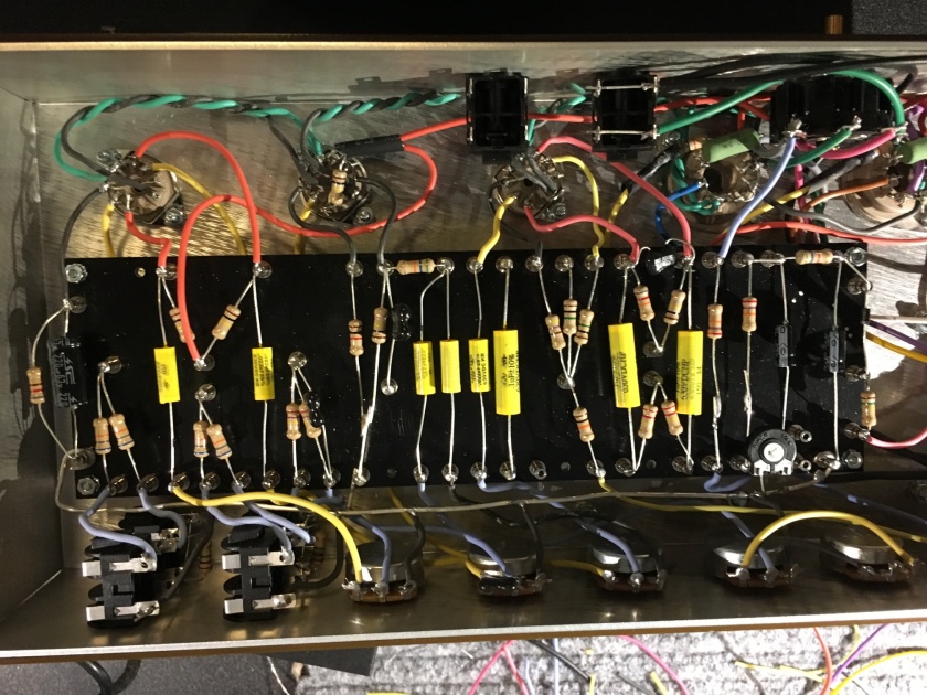
Now I felt that it was time for the board. Just follow the layout. I decided not to solder wires attaching to turrets close to the side from underneath. Better to see where they attach instead. Notice the thick ground bar at the bottom.
I noticed that many of the suggestions of mods to new Bluesbreaker 62 reissues like the choice of components was actually included in this kit.
The capacitors are Mallory 150 that allegedly will increase the clarity of the amp.
Resistors are carbon film, which ought to be replaced with carbon composition to get a slightly “richer” sound, but also a bit more noise. Referred as more “vintage” sounding. Which is better? Hard to make an A/B comparison unless we build a second amp and keep the first as a reference 🙂
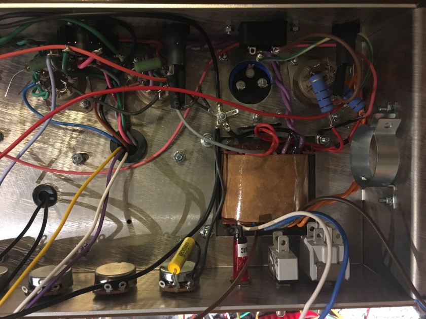
Dropped in the board and fixed it with 3 screws. The fourth hole is covered by the OT and could not be used.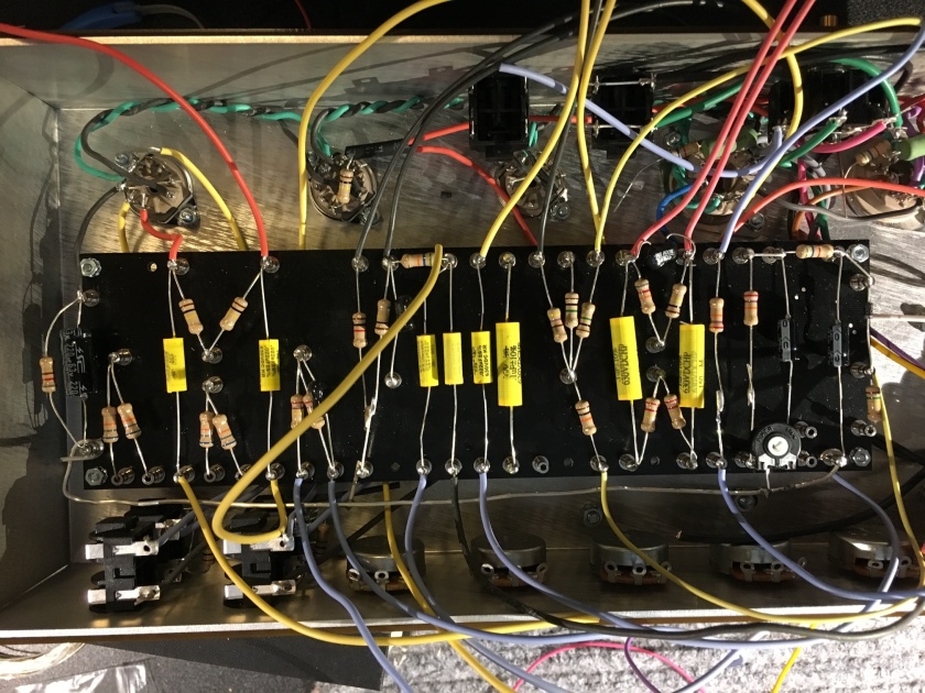
All wired up.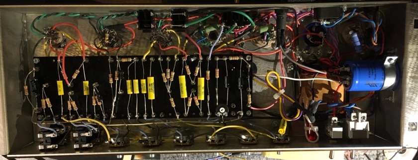
I bundled the yellow/purple wires from the OT (6600 turn) if I want to use KT66 some time in the future. They will then replace the brown and blue wires soldered to the power section tubes sockets.
Testing high voltage.
My test here are based on documentation from Tube Depot. Basically I test input voltage, high voltage section and then low voltage/board power.
First I made sure to use a RCD (residual current circuit breaker). Then with the standby and power switch set to off I turned on the current on the wall switch/RCD. The thing turned ON! I had installed the power breaker up side down. Well, everything looked fine so after a while I shut the power. Resoldered the breaker and installed the rectifier tube.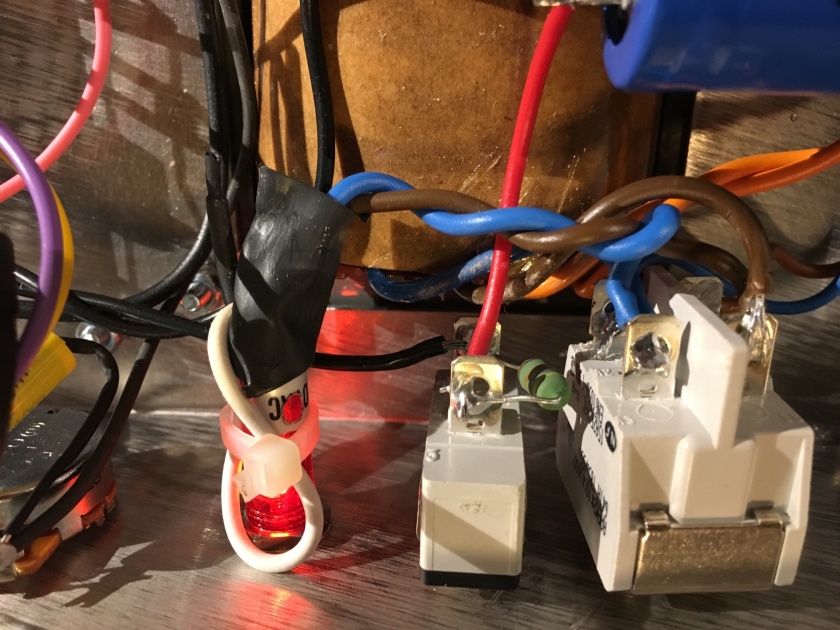
Checked voltage over the caps and input. All seemed well.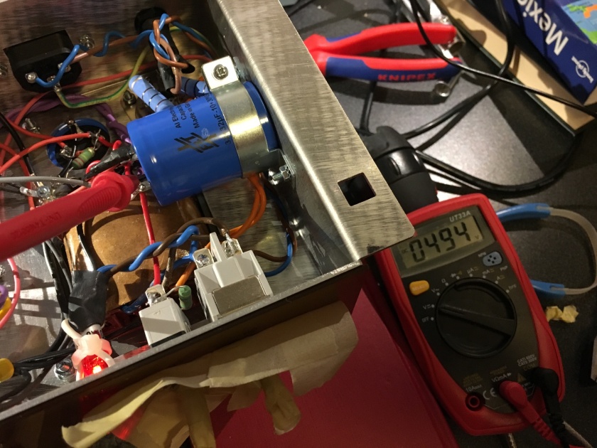
Had it running for some time and all looked well. After this I installed the preamp tubes and again, everything looked fine. Measured a few points according to the schematics and voltages seemed to be fine.
Text from raw sewage:
JJ ECC83 (which is what we got from TT). These are the next-best preamp tubes, and are generally more robust. That is, they are typically less microphonic, and often of very high quality. They tend to have a little less gain and a more round, mellow sound.
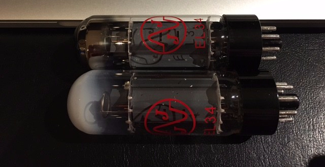
Unfortunately one of the power tubes was faulty. The top was all “milky” and the tube was dead. It was a mystery to me for quite some time how these tubes actually could have been shipped faulty when they had been measured. But then I learned that a tube will turn this way if there is an air leak. So the matched pair was measured and tested, then packaged. And somewhere in storage/shipment/manufacturing it started to leak and thus turned white.
TT shipped two new tubes to me, no problem.
Then new tube(s) arrived and I popped them in just to see what happened. No hum, both tubes lit up. So far so good. Jack in a guitar, speaker on 8 ohm and (with a pencil as a buffer) strummed the strings. Sounded like shit!!!! All distorted in a bad way, even with low volume/gain. then I remembered that bias is set to the minimum position.
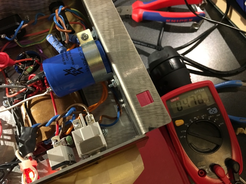
Powered off and let the tubes cool a bit. Then I inserted a tube probe (again from TubeTown) and searched the web for some guide on what mV I should set it to. Seems that 36mV was a common suggestion for the 470V version (which this seems to be – at least that is about what I measured on the big fat caps).
I turned on the amp and adjusted bias accordingly. Now the sound was much better!!! Seems that the bias dial is logarithmic. First nothing happened when I turned the needle, then after about 2/3 of the way it started to show some changes. Then very small changes gave a lot off mV movement. So being careful an letting the voltage settle I got it to 35.9
Then I gave it a good spin (until my kids came home from our neighbour). I will have to do a deep dive another day.
But, working and sounding good so far 🙂
Finally I got the time to crank it again. Hard to control the treble. Just need 1-2 on the high treble channel to add in sparkle. The normal channel is really nice. One thing though, test it loud with ear protection. Here is where the tone is happening.
Have a look at the modification suggestion page. I swapped a few components and now the amp is so sweet with really tamed treble. Also installed a PPMIV and now I can get some serious distortion from it as well if I want.
